XPCB Limited
Tel: +86-755-2301 2705
E-mail: info@apexpcb.com
Add:Building 3, JinFeng Industry Area, Heping Community, Fuyong Town, Baoan District, Shenzhen, 518103, China
Electronic components have electrical contacts, and the electrical connection between the two discrete contacts is called interconnection. Electronic equipment must be interconnected according to the circuit schematic to achieve the intended function.
A PCB as an integral part of the whole machine, generally cannot constitute an electronic product, there must be a problem of external connection. Electrical connections are required between PCB, PCB and off-board components, PCB and equipment panels. It is one of the important contents of PCB design to choose the best fit of reliability, technology and economy. There are many kinds of external connection modes, which should be chosen flexibly according to different characteristics.
Mode 1 Solder Welding method
The advantages of the Solder Welding connection is simple, low cost, high reliability, can avoid the failure caused by poor contact; the disadvantages are that the exchange, maintenance is not convenient enough. This approach is generally applicable to the case where the component has fewer external leads.
PCB electric conductor wire welding
This method does not require any connectors, as long as the pcb printed board with the external connection point directly with the components or other components outside the board can be soldered. such as speakers in the radio, battery boxes, etc.

Attention should be paid to the interconnection welding of circuit boards:
1)Welding wire pads should be as far as possible on the edge of pcb pcb printed board and arranged in a uniform size to facilitate welding and maintenance.
2)In order to improve the mechanical strength of the wire connection and avoid pulling the pad or printed wire off due to wire pulling, the wire should be drilled near the solder joint on the PCB printing plate to pass through the through hole from the welding surface of the PCB and then inserted into the pad hole from the component surface for welding.
3)Line or tie the wire neatly through a wire clip or other fastener with the plate to avoid breaking the wire by movement
PCB wire arrangement welding
The PCB printing board is connected by wire arrangement, which is reliable and not easy to be connected, and the relative position of the two pcb printing boards is not limited.
Directly welded between printed boards, this method is often used to connect a 90 degree angle between two printed boards. Connect to become an integral pcb pcb pcb part.
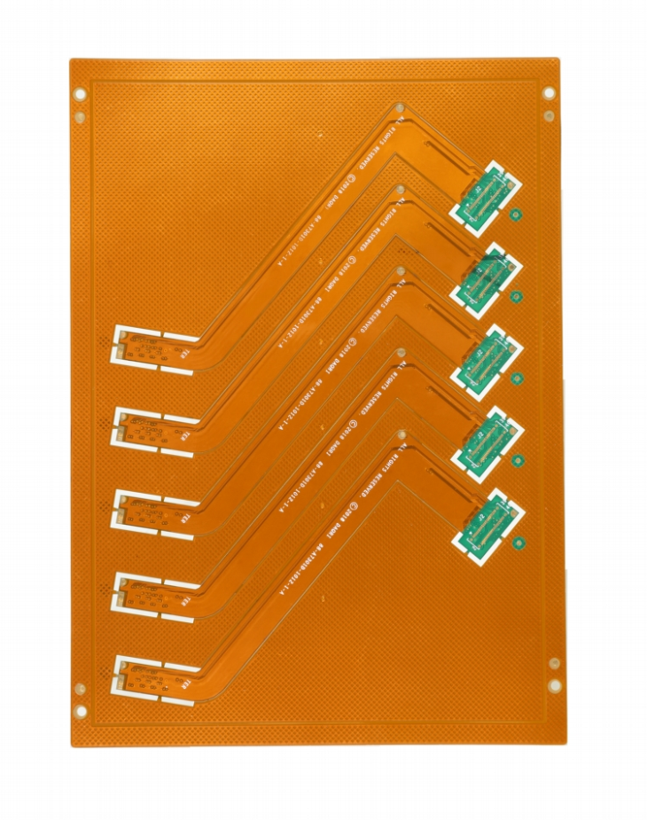
Mode 2 Connector connection
In the more complex instruments and equipment, it is often used to connect the connector. This “building block” structure not only ensures the quality of mass production of products, reduces the cost of the system, but also provides convenience for debugging and maintenance. When the equipment fails, the maintenance personnel do not have to check the component level (i.e., check the cause of the failure, trace back to the specific component. This work takes a considerable amount of time), as long as the judgment of which board is abnormal can be replaced immediately, in the shortest time to troubleshoot, shorten the downtime, improve the utilization of equipment. The replacement circuit board can be repaired in sufficient time and used as spare parts after repair.
PCB socket
This connection is often used in more complex instruments and equipment. This way is to make the printed plug from the edge of the pcb printed board. The plug part is designed according to the size of the socket, the number of contacts, the contact distance, the position of the positioning hole, etc., so that it can be matched with the special pcb printed board socket.
When making the plate, the plug part needs to be gold plated to improve the wear resistance and reduce the contact resistance. This way assembly is simple, interchangeability, good maintenance performance, suitable for standardized mass production. Its drawback is that the cost of PCB is improved, the manufacturing precision and process of PCB are high, the reliability is slightly poor, and the contact is often poor because the plug part is oxidized or the socket reed is aged. In order to improve the reliability of the external connection, the same lead line is usually drawn in parallel through the contacts on the same or both sides of the circuit board.
Standard pin connection
This method can be used for external connection of PCB, especially in small instruments. Two printed boards are connected by standard pin, and two printed boards are generally parallel or vertical, so it is easy to realize mass production.
XPCB Limited
Tel: +86-755-2301 2705
E-mail: info@apexpcb.com
Add: Building 3, JinFeng Industry Area, Heping Community, Fuyong Town, Baoan District, Shenzhen, 518103, China