XPCB Limited
Tel: +86-755-2301 2705
E-mail: info@apexpcb.com
Add:Building 3, JinFeng Industry Area, Heping Community, Fuyong Town, Baoan District, Shenzhen, 518103, China

After working with multiple tasks for a requiring client, I typically eliminate my anxiety by kicking it out at a neighborhood martial arts gym. When I was a teenager, I was rather versatile as well as had no trouble touchdown kicks. These days, nonetheless, my kicks are rather restrained by my stiff legs; I’m just not as adaptable as I utilized to be. Obviously, adaptability as well as rigidity are essential ideas beyond the fighting styles gym also. While developing PCBs, as an example, the selection of flex PCB versus rigid PCB can influence your entire technique.
In electronic devices field, you may find yourself moving from PCB to flexible f PCB, as the development of smart wearables as well as (IoT) requires electronics in form. Like it or otherwise, flexible PCB design skills are gradually coming to be an important skill in the electronic devices industry.
When as well as Why Should You Use Flex PCB?
While the manufacturing of flex PCBs may not be the most inexpensive, its adaptability enables a greater level of capability than what PCBs can attain. Being able to flex without breaking its track enables flex PCB to be fitted conveniently in smart wearables and gadgets with very minimal room.
Electronics created on flex PCBs are likewise much more durable, as the low mass of the PCB significantly lowers any type of risk of damages from resonances. Besides that, flexible circuit board are made from polyimide, which can endure severe temperature levels. This makes flex PCBs optimal for devices that run in high-heat atmospheres. Due to their various benefits, flex PCBs are expanding sought after within the electronics sector.
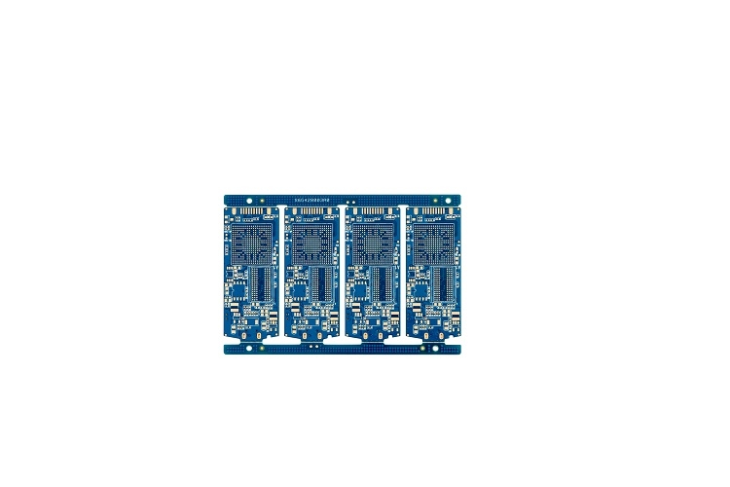
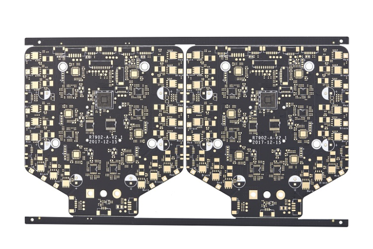
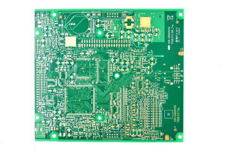
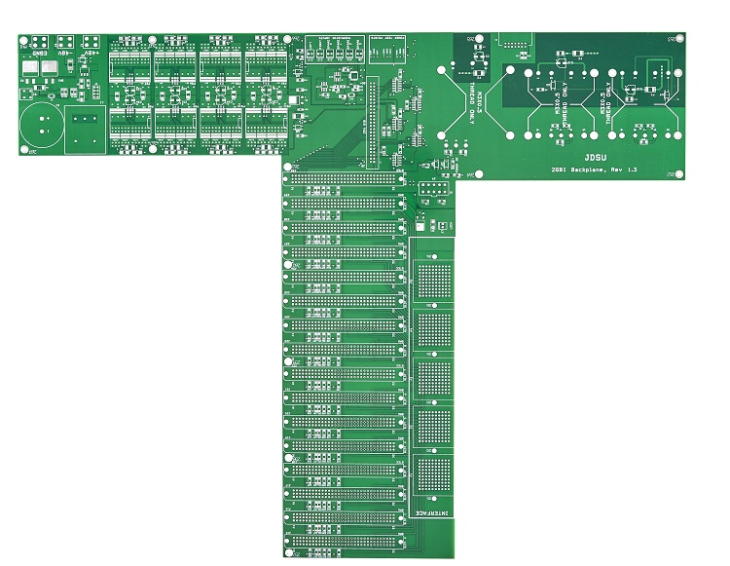
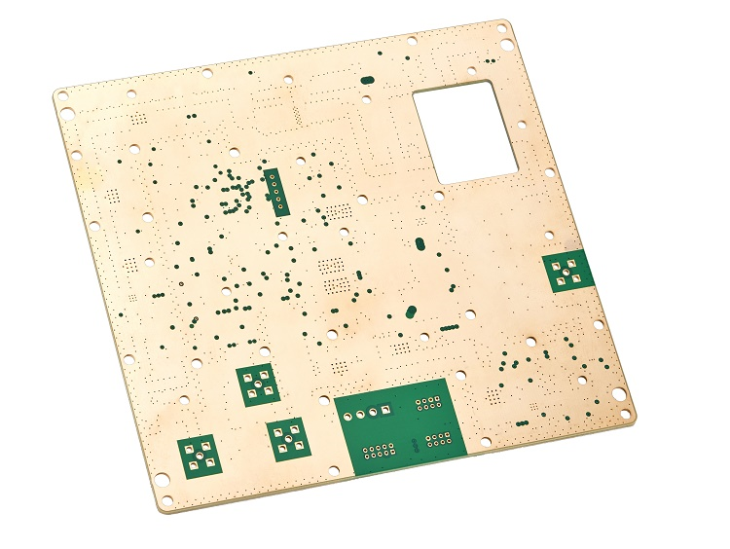
A circuit that has flex transmitting
It’s bend or break when it concerns flex PCB design.
Considerations When Designing With Flex PCB
When you’re dealing with a rigid PCB, your worries possibly entail pressing hundreds of parts right into a little PCB or making certain that analog are appropriately divided from electronic ones. In rigid PCB design, your concerns are purely electronics-based. When you move to flex PCB layout, these problems shift too.
Originally made use of worldwide War II age, flex PCBs were originally made to replace hand-built wire harnesses that were prone to human mistake. The little strips of copper in flex PCBs enable high-density links. Nonetheless, electronics abilities alone are not nearly enough to construct flex PCBs; mechanical understanding is needed, as copper tracks as well as components go through mechanical tension due to the nature of the flex PCB.
A crucial standard when designing with flex PCB is the bend proportion. Expressed as a proportion of bend radius versus the flex PCB density, the bend ratio can not dip below a minimal threshold. If the bend ratio dips, the circuit becomes at risk to mechanical failing. Additionally, the bend area of the flex PCB is particularly adjustments in copper size or. Vias in the bend location ought to likewise be avoided at all price.
Together with these considerations, below are additional flex PCB design ideas to assist you minimize production defects:
Stay Clear Of I-Beam Stacking: In rigid PCB layout, you can have traces running parallel on top of each other on top and also lower layers with no problems. Yet when you’re creating flexible PCBs, traces ought to not be piled on top of each other as this can lower circuit flexibility.
Routing Corners in Bend Area: When you’re transmitting corners in a rigid PCB, your problem is whether right-angled corners create electro-magnetic interference (EMI) or generate heat points in a high current circuit. The form of the tracks in the bend location can conveniently make or break your flex PCB. Preventing transforming the track direction in the bend location is always suggested. If adjustment is unpreventable, a soft edge is preferred rather than the common 45 ° sharp corner in rigid PCBs.
Compression Versus Extending: In rigid PCBs, there are commonly no tough rules regarding transmitting little conductors less than 7 mils. Nonetheless, in flex PCB layout, the impacts of compression and also stretching need to be taken into consideration. Directing tiny conductors on the internal side of the bend can lower the likelihood of track damages, as smaller conductors much better endure being compressed than being stretched.
Make Conductor Width Larger When Feasible: Flex PCB saves precious area in your electronic devices. However if you believe having small tracks is a great technique, you could not be better from the truth. The guideline with track size is that it needs to go to the very least five times the density of the copper foil of the flex PCB. You must make this rule suitable for all your tracks, other than in specific circumstances where they require to press via the tiny rooms between pads.
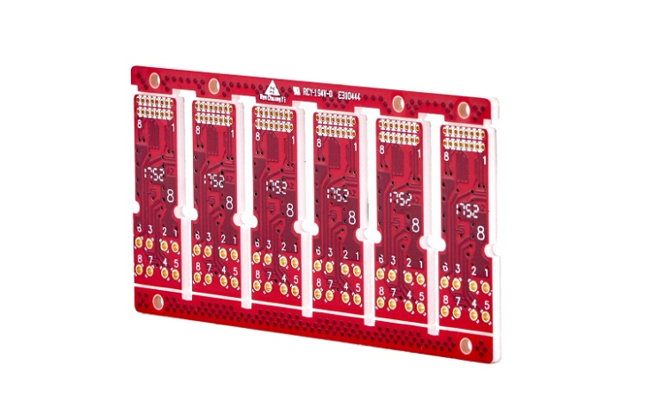
Diverse tinted and also various size circuitry traces
Arm yourself with the ideal electrical wiring and also routing that’ll get the job done for your styles.
Working with flex PCBs can be easier with PCB design software made to boost your adaptability without extra limitations. Need more help with your flex PCB layout? Get in touch with a specialist at XPCB.
XPCB Limited
Tel: +86-755-2301 2705
E-mail: info@apexpcb.com
Add: Building 3, JinFeng Industry Area, Heping Community, Fuyong Town, Baoan District, Shenzhen, 518103, China